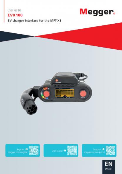
ENENGLISHUSER GUIDEEVX100EV charger interface for the MFT-X1Register megger.com/registerUser Guide Support megger.com/support
This document is copyright of:Megger Limited, Archcliffe Road, Dover, Kent CT17 9EN. ENGLAND T +44 (0)1304 502101 F +44 (0)1304 207342 www.megger.comMegger Ltd reserves the right to alter the specification of its products from time to time without notice. Although every effort is made to ensure the accuracy of the information contained within this document it is not warranted or represented by Megger Ltd. to be a complete and up - to - date description.For Patent information about this instrument refer to the following web site: megger.com/patentswww.megger.comEVX1002
Declaration of ConformityHereby, Megger Instruments Limited declares that radio equipment manufactured by Megger Instruments Limited described in this user guide is in compliance with Directive 2014/53/EU. Other equipment manufactured by Megger Instruments Limited described in this user guide is in compliance with Directives 2014/30/EU and 2014/35/EU where they apply.The full text of Megger Instruments EU declarations of conformity are available at the following internet address: megger.com/eu-dofc This manual supersedes all previous issues of this manual. Please ensure that you are using the most recent issue of this document. Destroy any copies that are of an older issue.www.megger.comEVX1003
www.megger.comEVX1004Contents1. Introduction ....................................................................................................................51.1 Company web site .......................................................................................................................52. Safety Warnings and Standards ....................................................................................62.1 Warnings, Cautions and Notes ...................................................................................................62.2 Safety warnings ...........................................................................................................................62.2.1 Installation category definitions: ................................................................................................72.3 Safety, Hazard and Warning symbols on the instrument .........................................................73. Overview .........................................................................................................................83.1 EVX100 layout .............................................................................................................................83.2 EVSE (Charger) Status codes .......................................................................................................84. Operation .......................................................................................................................94.1 Battery status and charging .......................................................................................................104.2 Charging the EVX100 ..................................................................................................................104.3 Hot keys: ......................................................................................................................................104.4 Updating the MFT-X1 firmware .................................................................................................105. Testing the EV charger ...................................................................................................115.1 Connecting the EVX adaptor and power ON/OFF .....................................................................115.2 MFT-X1 connection errors ...........................................................................................................125.3 Manual battery status check on the EVX100 .............................................................................126. Testing with the EVX ......................................................................................................136.1 Testing for live voltages across terminals ..................................................................................136.2 Phase sequence ...........................................................................................................................136.3 PE and CP error mode testing ....................................................................................................136.4 Testing for PE earthing issues .....................................................................................................146.5 Testing loop impedance ..............................................................................................................146.6 Loop impedance hot key options available with the EVX100: .................................................156.7 Running a loop impedance test: ................................................................................................166.8 Testing RCD and RDC functionality ............................................................................................176.8.1 RCD testing Hot keys: ...............................................................................................................176.9 Testing the RCD/RDC ...................................................................................................................187. Supply requirements ......................................................................................................198. Accessories ......................................................................................................................208.1 Included accessories ....................................................................................................................208.2 Optional accessories ....................................................................................................................208.3 Maintenance: ...............................................................................................................................208.4 Cleaning ......................................................................................................................................209. Repair and Warranty ......................................................................................................219.1 Repair ...........................................................................................................................................219.2 Return procedure ........................................................................................................................219.3 UK Service Centre .......................................................................................................................2110. WEEE Directive ............................................................................................................2210.1 Battery disposal ........................................................................................................................22
www.megger.comEVX1005Introduction1. IntroductionThank you for purchasing the Megger EVX100 (Electric Vehicle Charge-point Adaptor). For your own safety and to get the maximum benefit from your instrument, please ensure that you read and understand the following safety warnings and instructions before using the instrument. This user guide describes the operation and functions of the EVX100 Electric Vehicle Charge point Adaptor when used with the MFT-X1 multi-function tester to test EVSE units (Electric Vehicle Supply Equipment).Megger Limited reserves the right to change the specification of these instruments at any time without notice. Megger reserves the right to improve the content of this User Guide from time to time without notice. Megger reserves and retains the intellectual property rights of the content including the design, text, graphics, and logos in this User Guide. Any partial or complete reproduction or usage of the content is strictly prohibited. To register this instrument please visit Megger.com/register1.1 Company web siteOccasionally an information bulletin may be issued via the Megger web site. This may concern new accessories, new usage instructions or a software update. Please occasionally check on the Megger web site for anything applicable to your Megger instruments.www.megger.comIMPORTANT!Update your MFT-X1 firmware before using the EVX100.megger.com/mft-x1Refer to MFT-X series User Guide for installation instructionsCharge battery before first use
www.megger.comEVX1006Safety Warnings and Standards2. Safety Warnings and StandardsThese safety warnings must be read and understood before the instrument is used. Retain for future reference.EVSE: Electric Vehicle Supply (Charging) Equipment2.1 Warnings, Cautions and NotesThis user guide follows the internationally recognised definition. These instructions must be adhered to at all times.DescriptionWARNING : Indicates a potentially dangerous situation which, if ignored, could lead to death, serious injury or health problems. CAUTION : Indicates a situation which could lead to damage of the equipment or environmentNOTE : Indicates important instructions to be followed to perform the relevant process safely and efficiently.2.2 Safety warnings The equipment must be used only by suitably trained and competent persons. National Health and Safety Legislation requires users of this equipment or their employer to carry out valid risk assessment of all work so as to identify potential sources of danger and to mitigate risk. If this equipment is modified or used in a manner other than specified by the manufacturer, the protection provided by the equipment may be impaired. This equipment is not intrinsically safe and must not be used in hazardous atmospheres. This equipment is for indoor and outdoor use up to 2000 m altitude. It must not be used in wet conditions or outside the specified temperature range. If the equipment gets wet, disconnect and do not use. Clean equipment with a dry, clean cloth. Inspect the equipment for damage before each use. The equipment must not be used if any part of it is damaged. Voltage measurements must not be relied on, and independent means used to verify whether circuits are energised. If no voltage is measured, this may be because an EVX’s internal fuse has blown. Do not use the EVX if the MFT fails to detect it. Continuity of protective conductors and earthed equipotential bonding of new or modified installations must be verified before powering up the EVSE to be tested. Plug in the EVX to the MFT before connecting to the EVSE to be tested. Similarly, disconnect from the EVSE before unplugging the EVX and MFT. Do not connect USB cable when EVX is connected to EVSE. Use only Megger approved adapters with this product.
www.megger.comEVX1007Safety Warnings and Standards No user serviceable parts are inside the equipment. Refer repairs to Megger approved service centres. This equipment contains a lithium-ion battery. Do not heat or dispose of the product in a fire. At the end of the equipment’s life dispose of it according to local regulations for recycling. Do not dispose of this equipment to landfill. Ensure that the working environment is safe from moving vehicles. Beware of the connector cable which can be a trip hazard.2.2.1 Installation category definitions:CAT IV - Measurement category IV: Equipment connected between the origin of the low-voltage mains supply and the distribution panel.CAT III - Measurement category III: Equipment connected between the distribution panel and electrical outlets.CAT II - Measurement category II: Equipment connected between the electrical outlets and the user’s equipment.Measurement equipment may be safely connected only to circuits at the marked rating or lower.2.3 Safety, Hazard and Warning symbols on the instrumentThis paragraph details the various safety and hazard icons on the instrument’s outer case.Icon DescriptionFWarning: High Voltage, risk of electric shockGCaution: Refer to user guide.UK conformity. This equipment complies with current UK legislationEU conformity. Equipment complies with current EU directives.Do not dispose of to landfill, in sewage systems or by fire.Follow local recycling guidelines for Lithium-Ion batteriesDirect Current supplyWith respect to earth (ground)
www.megger.comEVX1008Overview3. Overview3.1 EVX100 layout12ItemDescription1 Battery level check button2 LED indicator3.2 EVSE (Charger) Status codesThe following list explains the EV charger status codes reported by the MFT-X1 when using the EVX100. Most of these codes will only appear momentarily during a tripping test sequence. For normal operation with the MFT-X1 switched on and the EVX100 connected to a working charger the EV charger will be in state C2.Status CodeDescriptionAction requiredEVSEEVX100 not connected to Charger or Charger not detected.Check utility supply to Charger.A1/A2 Charger not ready.Displayed when the EVX100 is cycling through A/B/C codes to reset charger after tripping test.B1EVX detected.Charger not ready to suppply energy. B2EVX detected.Charger ready to supply energy (connector interlock should be engaged).Displayed during RCD or RDC trip automatic resetting sequence.C1EVX comms established with charger. Green EVX flashing light.Charger not ready to supply energy.Rare - this is normally a fault condition of the charger. The EVX100 cannot set the charger into C2 charging active mode.C2EVX connected and active - Charger output active.This is the normal operating state before any tripping test is applied.EError state. Usually loss of utility power. Also possible loss of utility supply.Charge EVX100 and MFT-X1. Check utility supply before restesting.FFault. Usually generated during a CP or PE error state.
www.megger.comEVX1009Operation 4. Operation NOTE : The EVX100 MUST be charged before use else the unit will not operate. This is required as international shipping prevents Li-ion battery operated equipment being shipped with more than 30% charge. Designed for testing Mode 3 AC electric vehicle chargers (EVSEs), the Electric Vehicle Charge-point Adaptor, EVX100, is a compact and portable unit, designed to be fitted directly to the front of the MFT-X1. This removes the need for any intermediate manual adaptors between the MFT and the charge point and transfers control of the charger point to the MFT-X1.When connected to the MFT-X1 the EVX100 automatically activates an EV charger configuration, removing unnecessary test modes from the MFT menu option. This reduces complexity and test times and accelerates familiarity.Unlike most EV charger adaptors, the EVX100 is IP54 so suitable for use in inclement weather.The adaptor allows direct control of the EV charger from the MFT-X1, with access to Control Pilot status reporting.The EVX100 has been specifically designed to aid in the testing of charging points in accordance with the IEC/EN 61851-1, IEC 62955 and IEC/HD 60364-7-722 standards.The EVX100 attached to the MFT-X1 multifunction testerDisplay content and functionality
www.megger.comEVX10010Operation 4.1 Battery status and chargingNOTE : The EVX must be fully charged before use.If the EVX100 is fully charged the LED will flash Green, Yellow or Red every 10 seconds indicating battery status, as below:Green:100% to 50% charge remainingYellow:50% to 20% charge remainingRed:<20% charge remainingHolding down the button on the top of the EVX100 will also show battery status.4.2 Charging the EVX100NOTE : The EVX100 will only charge over an ambient temperature range of 0 ºC to 45 ºC.Charging the EVX100 battery status is performed using a type C USB cable.1. Disconnect the EVX100 from the EV charger.2. With the EVX100 removed from the MFT-X1 the USB-C charging port is exposed. To charge the EVX100 connect the adaptor to a suitable USB-C source.The Charge status is indicated by the top LED. Solid GREENEVX100 is chargedFlashing GREENEVX100 is chargingRed:A charging error has occurred – contact Megger technical support4.3 Hot keys:Hot key functionality is a subset of those offered on the MFT-X1 under normal operating conditions, i.e. non-EVX mode. Hot key functionality varies with the individual test modes selected. Refer to the individual test mode below for details of hot key functions.Hot key options can also be selected using the right rotary knob. Pre-test inspection and verification requirements.WARNING : The EVX100 performs live testing of the EV charger. Consequently, before the EVX100 is connected to the EV Charger all the standard tests that would be carried out on any newly installed circuit should be complete before the equipment is made live.4.4 Updating the MFT-X1 firmwareThe MFT-X1 must be upgraded to the latest version of firmware to ensure the EVX100 will operate. For full details of updating the MFT-X1 firmware visit www.megger.com/mft-x1. On the MFT-X1 product page select the Product Support tab, then select Software and Firmware updates from the right-hand options list. Follow the instructions to download the latest firmware update.NOTE : The Update process requires a micro-SD card to transfer the .BIN file to the MFT-X1.
www.megger.comEVX10011Testing the EV charger5. Testing the EV chargerThe EVX100 takes control of the Control Pilot during the testing process. The operator has no need to manually change the Control Pilot status, other than when performing Control Pilot error testing.The Proximity Pilot (PP) is set to 13 A for all testing purposes.NOTE : To simplify the testing process the EVX automatically disables functionality not available through the adaptor. These are: Insulation, continuity, current clamp and Earth testing.5.1 Connecting the EVX adaptor and power ON/OFFEnsure the EVX100 shows no sign of damage to the case or connection cable.1. Insert the EVX adaptor to the MFT-X1. The adaptor will only fit in one orientation. Do not force the adaptor, but be aware that it is a snug fit.2. Connect the EVX connector plug to the EV charger. The EVX100 is now ready to establish communications with the EV Charger. 3. Turn the left rotary dial on the MFT-X1 to the Voltage setting. NOTE : This will also switch on the EVX100 and the EV charger.4. On the EVX100, the top LED will flash yellow. This indicates that the EVX100 is establishing communications with the MFT-X1.5. After a few seconds the LED will stop flashing yellow, indicating successful connection to the MFT-X1.
www.megger.comEVX10012Testing the EV charger6. The EVX100 will now send a status sequence of A, B and C to the charger. This is shown at the bottom of the MFT-X1 display. 7. The charger should lock the connector in place and the MFT-X1 will display the single or 3 phase voltages of the charger output.EV voltage status8. The EVX100 LED will now flash GREEN, YELLOW or RED once every 10 seconds depending on it’s charge status.NOTE : Many chargers have a startup delay of up to 5 minutes. If this is the case them most of these chargers have a “Start charging now” option on the EV charger. Pressing this button should switch the charger into charging mode (State C). 5.2 MFT-X1 connection errorsAfter switching on the MFT-X1 the EVX100 LED continues to rapidly flash Yellow for more than 30seconds, the EVX has not established connection to the MFT.In this situation:1. Switch off the MFT-X1.2. Remove the EVX100 from the MFT and re-insert to the MFT.3. Switch the MFT-X1 to Volts and wait for the LED again. 4. If the MFT still does not make connection to the EVX100 contact Megger technical support: uksupport@megger.com or +44 (0) 1304 502 1025.3 Manual battery status check on the EVX100The charger status can be manually checked at any time by holding down the power button on the top of on the adaptor. The LED battery status light on the top of the EVX will indicate charge status. See 4.1 Battery status and charging on page 10.
www.megger.comEVX10013Testing with the EVX6. Testing with the EVX6.1 Testing for live voltages across terminalsThe EVX can test between single phase, Neutral and Earth on a single-phase charger or all three phases in a three-phase charger. To swap between phases:1. Ensure the EVX is connected to the MFT-X1 and the charger is in State C as indicated in the display.2. Identify the connection option you wish to measure. Options are: L1, L2, L3 or L1-L2-L33. Press Hot key 5 to change the phase connection.4. The MFT-X1 shall display the voltages relevant to the phase selected.Voltage displayNOTE : Selecting a phase with no voltage, or L1-L2-L3 on a single-phase supply will cause unconnected terminals to float to intermediate voltages.6.2 Phase sequenceOn a 3-phase charger the MFT-X1 will automatically show the phase sequence in the display when it detects a compliant 3-phase connection.The MFT-X1 will show either L1-L2-L3 or L3-L2-L1 depending on the phase sequence.6.3 PE and CP error mode testingThe PE and CP error test generates a PE or CP error code that disables the EV charger. Once in the disabled state, the charger is sent a state A, B and C to set it back to a charging state. To test the PE or CP error response:1. Ensure the MFT-X1, and EVX100 are in voltage mode and the MFT is displaying State C2.2. Press the Hot key 1 to select PE or CP error.3. Hold down the TEST button. The EV charger should be disabled and the display show 0 V on the live terminals.4. Release the TEST button. The charger should then return to State C2 and the voltages appear on the charger terminals.
www.megger.comEVX10014Testing with the EVX6.4 Testing for PE earthing issuesThe PE error function detects the presence of earthing issues through the EV charger that can affect the safe use of the MFT-X1. To test for PE errors ensure:1. The EVX100 is connected to the MFT-X1 and communications have been established as above and the charger is in charging state C.2. Switch the MFT-X1 to the Loop impedance mode.3. Switch Hot key 5 to the L-PE option.4. Ensure the display shows the presence of 230 V AC on the voltage widget triangle.5. Touch, but DO NOT PRESS, one of the red TEST buttons on the MFT. If an issue exists with the PE bonding the MFT-X1 shall display the PE warning as below and the test will not run.PE warning No warning symbol indicates it is safe to proceed with live testing.NOTE : The PE inhibit function can be disabled in SETTINGS by setting the PE Confirmation to OFF. However, the warning will always be displayed.6.5 Testing loop impedanceLoop impedance is tested in the same way as on the standard MFT-X1 without the EVX adaptor. For full details of loop impedance testing refer the full MFT-X1 user manual.The EVX100 limits functionality to those tests suitable for use on an EV charger, as below:
www.megger.comEVX10015Testing with the EVX6.6 Loop impedance hot key options available with the EVX100:Hot key options available are:Hot key 1:Z:Shows the loop impedance value for the connection selected on hot key 5Zmax:Shows the latest loop impedance value and also the highest value recorded if more than one measurement is madeZref:Used to remove loop impedance values such as Ze from the measured value.Vdrop: Used with Zref and I-Vdrop settings to measure the volt-drop at the charger under full load conditions. Hot key 2:Select between the RCD protection type fitted to the EV charger. These are:RDC EV:Used for testing L-PE circuits on chargers fitted with an RDC-DD deviceRCD: Use for testing L-PE circuits protected by a type B RCD.NO RCD: Used for all other connection options, L1-N, L2-N, L1-L2, L1-L3, L2-L3, where tripping an RCD is not possible.Hot key 3:Displays the connection recommendations and invalid test chart for Hot key 2 and Hot key 5 combinations.Hot key 4:Select either:3 wire: (recommended for L-PE testing) or 2 wire: For all other loop test optionsHot key 5:The connection options for testing loop impedance on a charger are:L1-PE, L1-N, L2-PE, L2-N, L3-PE, L3-N, L1-L2, L1-L3 or L2-L3.
www.megger.comEVX10016Testing with the EVX6.7 Running a loop impedance test:To perform any Loop impedance measurements on the EV charger the charger must be in State C2. The EVX will automatically set the charger to this state when the MFT-X1 and the EVX are connected and switched on.NOTE : The hands-free automatic Loop test does not operate with the EVX connected.1. Ensure the EVX is connected to the MFT-X1.2. Connect the test lead from the EVX to the EV charger if not already connected.3. Select the Loop test function on the left rotary knob of the MFT-X1. 4. The EV Charger should switch to State C2 and live voltage should be indicated in the voltage widget on the MFT display as below:Loop mode widget shows live voltsNOTE : The Interlock should also engage on the EV charger to prevent the EVX connector from being disconnected from the EV charger.5. Press Hot key 1 to select Z6. Press Hot key 5 to select the circuit connection you wish to test, either: L1-PE, L1-N, L2-PE, L2-N, L3-PE, L3-N, L1-L2, L2-L3, L1-L3.7. Press Hot key 4 to select either 3 wire or 2 wire depending on the type of test being run. e.g. For a L-PE test you can select 3 wire. For a L-N or L-L test select 2 wire. 8. For testing L-PE circuits select RDC EV or RCD on Hot Key 2 depending on the protection device in the EV charger. If testing L-N or L-L circuits select NO RCD on Hot key 2 9. Select L-PE on Hot key 510. Select the circuit path to be tested using Hot key 4 as below:11. For 7 kW or lower EV chargers select L1-PE (usually single phase chargers)12. For >7kW chargers (usually 3 phase chargers) select L1-PE, L2-PE or L3-PE for earth loop impedance testing, or L-N, L1-L2, L2-L3 or L1-L3 for multi-phase testing.13. Touch the TEST button and verify no PE or Reverse L-N error is generated. If a PE error is displayed the earthing of the EV charger should be checked for bonding errors. If an L-N swapped error is displayed verify the live conductors are not swapped in the supply to the charger.NOTE : Both of these warnings will inhibit the MFT-X1 from performing a loop measurement.NOTE : The L-N swapped warning and inhibit can be disabled in SETTINGS for the MFT-X1.
www.megger.comEVX10017Testing with the EVX14. Press the TEST button. The MFT-X1 should display the loop impedance for the circuit being tested.Image loop test on L-PEShould an RCD or RDC trip during the measurement mode, the EV charger will lose power and switch off. The EVX100 will automatically attempt to reset the EV charger by sending the Status sequence: C, B, A, B, C. It will continue to send this until the EV charger returns to state C. The tripped RCD should be reset. If the RDC tripped this should reset automatically. The MFT-X1 should then restore the EV charger to state C.6.8 Testing RCD and RDC functionalityChargers fitted with RCD type B or a combination of RCD type A and a RDC-DD can be tested with the EVX100. IMPORTANT: Location of the protective devices and the type of protection is very important as the devices will need to be reset once tripped. The charger will most likely need to be removed from any controlling back-office software/network, as this may prevent the charger from restarting when the RCD or RDC is reset or prevent the RDC from resetting automatically RDC-DD devices are usually self-resetting. If an RDC does not reset it is likely the charger is being controlled remotely. RCDs are not self-resetting and will need to be manually reset. These could be located in the EV charger, in a local sub-board or in the main distribution board.6.8.1 RCD testing Hot keys:Hot key 1:Not usedHot key 2: EV A/B or EV A/RDCHot key 3:Not usedHot key 4:Preset depending on Hot key 2Hot key 5:Circuit connection – L1-PE, L2-PE, L3-PE.
www.megger.comEVX10018Testing with the EVX6.9 Testing the RCD/RDCThe EVX100 offers automatic test sequences for RCD and RDC testing. If only a part of the sequence needs to be run, the AUTO sequence can be modified in SETTINGS RCD tab – refer to the full MFT-X1 user manual.1. Ensure the EV charger is connected to the EVX100 and the MFT-X12. Switch the MFT-X1 left rotary knob to RCD. The charger should enter Mode C2 as displayed on the MFT-X1.The Voltage widget should display live voltages.If the charger terminals are not live the charger may need to be manually switched to the charging mode. Refer to manufacturers’ instructions for the charger for over-riding the random delayed start function in the charger settings..3. Set Hot key 2 to EV A/B or EV A/RDC depending on the devices protecting the EV charger4. Set Hot key 5 to L1-PE, L2-PE, L3-PE as required.5. Press the TEST button. The MFT-X1 should start the test sequence.6. Each time the EVX/MFT trips the RCD or RDC the instrument will try to reset the charger. to state C2. Chargers with internal RCD and RDC or Type B RCDs may reset automatically. Installations with external RCDs will need the RCD to be reset manually.NOTE : A DC ramp test to be performed at the end to discover the DC tripping current. For a Type B RCD the DC tripping current must be less than twice the rated current for AC (i.e. 60 mA DC for a 30 mA RCD), so results around 40 mA are commonly displayed.7. At the end of the test sequence the MFT-X1 will display a complete test sequence as below:Completed sequenceThe last tripped device should be reset and the MFT-X1 will return the EV charger to State C2.NOTE : 1. Any faults on the earthing can produce a PE warning and prevent the test from proceeding2. Some EV chargers isolate all terminals when tripped, including the earth terminal. The voltage on the earth terminal may confuse the MFT-X1 and report an RE high error. Contact Megger technical services for further advice.
www.megger.comEVX10019Supply requirements7. Supply requirementsPower supply:Internal battery:Li-ion 3180 mAH Recharging:Type C USB (required supply is 5 V, 1 A maximum)Charging status:LEDInput voltage230 V AC nominalmax 253 V AC400 V AC nominalmax 440 V ACInput frequency:50/60 HzCP state verification:A1, A2, B1, B2, C1, C2, E, FFor measurement specification refer to the MFT-X1 user guide. See megger.com/mft-x1NOTE : Uses the Megger Confidence Meter to measure the supply source impedance of circuits protected with an RCD rated ≥30 mA when there are only two connections possible. When a neutral is available the three-wire test will provide a quicker, more accurate result.NOTE : RCD may trip if there are high leakage currents in the circuit under test. This measurement is immune to the effect of inductance found in some RCDs as it measures resistance (RCD Uplift). EN61557-3 Measurement Range: 1.00 Ω to 1999 ΩConnection options:Fixed type 2: IEC 62196-1Safety:IEC61010-1:2010 61010-031:2015, CAT II 250 VTemperature range:Working range:-10 °C to +55 °CStorage range:-25 °C to +70 °CHumidity range:90% R.H at +40 °C maxIngress protection:IEC 60529: IP 54: Equipment is protected against ingress of dust and water splashes and is suitable for indoor and outdoor use.Vibration:MIL-PRF-28800F: Class 2Maximum operating altitude:2000 mPollution degree:2MechanicalEVX case dimensions: 133.5 x 115 x 56 mm (5.2 x 4.5 x 2.2 inches) excl. cable.Unpackaged weight:976 gPackaged dimensions:350 x 280 x 75 mm (13.8 x 11.02 x 2.96 inches)Packaged weight:1580 g Cable length:2 m
www.megger.comEVX10020Accessories8. Accessories8.1 Included accessoriesItemOrder No.EVX100 adaptor with type 2 plug1016-183EVX100 carry case2017-285User guide2017-2878.2 Optional accessoriesItemOrder No.EVX100 carry case2017-285Type 1 to type 2 adaptor1014-9018.3 Maintenance:Do not open the adapter case. It contains no user-serviceable parts. Repair or servicing should be performed only by qualified personnel. Refer to www.megger.com/support8.4 Cleaning Should the EVX100 or the charge plug or cable require cleaning they can be wiped down using a damp cloth. Never clean the adaptor or plug when connected to any measurement circuit. Never clean the adaptor or plug when connected to any test equipment. Never use the adaptor or plug until they have dried completely. Dirty leads should be cleaned with a clean cloth dampened with either water or isopropyl alcohol (IPA). Wipe the instrument with a clean cloth dampened with either water or isopropyl alcohol (IPA). Wipe the leads and instrument using a clean, dry cloth to remove excess liquid.
www.megger.comEVX10021Repair and Warranty9. Repair and WarrantyThis product is warranted to the original purchaser against defects in material and workmanship for one year from the date of purchase. During this warranty, the manufacturer will either replace or repair the defective unit, subject to verification of the defect or malfunction. This warranty does not cover damage from abuse, neglect, accident, unauthorised repair, alteration, contamination, or abnormal conditions of operation or handling. Any implied warranties arising out of the sale of this product, including but not limited to implied warranties of merchantability and fitness for a particular purpose, are limited to the above. The manufacturer shall not be liable for loss of use of the instrument or other incidental or consequential damages, expenses, or economic loss, or for any claim or claims for such damage, expense or economic loss. Some states or countries laws vary, so the above limitations or exclusions.9.1 RepairMegger operate fully traceable calibration and repair facilities to make sure your instrument continues to provide the high standard of performance and workmanship that is expected. These facilities are complemented by a worldwide network of approved repair and calibration companies, which offer excellent in-service care for your Megger products.For service requirements for Megger instruments contact: Megger Limited, Archcliffe Road, Dover, Kent CT17 9EN U.K. Tel: +44 (0) 1304 502 2439.2 Return procedureWARNING : DO NOT remove the battery cells before shipping this instrument. The EVX100 cannot be shipped by air freight. Faulty battery modules MUST NOT be shipped to Megger or anywhere else. Please contact the Megger service department before shipping faulty modules9.3 UK Service Centre 1. When an instrument requires recalibration, or in the event of a repair being necessary, a Returns Authorisation (RA) number must first be obtained from one of the addresses shown above. The following information is to be provided to enable the Service Department to prepare in advance for receipt of your instrument and to provide the best possible service to you: Model (for example, EVX100). Serial number (found on the device information). Reason for return (for example, calibration required, or repair). Details of the fault if the instrument is to be repaired. 2. Make a note of the RA number. A returns label can be emailed or faxed to you if required. 3. Pack the instrument carefully to prevent damage in transit. 4. Before the instrument is sent to Megger, freight paid, make sure that the returns label is attached or that the RA number is clearly marked on the outside of the package and on any correspondence. Copies of the original purchase invoice and packing note should be sent simultaneously by airmail to expedite clearance through customs. In the case of instruments which require repair outside the warranty period, an immediate quotation can be provided when obtaining the RA number. 5. Track the progress on line at www.megger.com
www.megger.comEVX10022WEEE Directive 10. WEEE Directive The crossed out wheeled bin symbol on the instrument is a reminder not to dispose of the product with general waste at the end of life. Megger is registered in the UK as a Producer of Electrical and Electronic equipment. The registration No is; WEE/DJ2235XR. Users of Megger products in the UK may dispose of them at the end of their useful life by contacting B2B Compliance at www.b2bcompliance.org.uk or by telephone on 01691 676124. Users of Megger products in other regions should contact their local Megger office or distributor. 10.1 Battery disposal The battery in this equipment is not customer serviceable.The crossed out wheeled bin symbol placed on a battery is a reminder not to dispose of batteries with general waste when they reach the end of their usable life. For disposal of batteries in other parts of the EU contact your local Megger branch or distributor. Megger is registered in the UK as a producer of batteries (registration No.: BPRN00142). For further information see www.megger.com
www.megger.comEVX10023WEEE Directive Online electrical certification softwareCertSuite Installation30 Day FREE Trialat CertSuite.info Visit Certsuite.info for more information Or scan the QR code ➔ ■Quick, reliable and flexible – works on any device in any location ■Unlimited certificate generation ■Free technical support ■Secure Microsoft® Azure® cloud storage ■Multiple user access (licence required per user) ■Electrical, fire, lighting, PV, EV certificates ■Attach photographs to bespoke certificatesiOS
www.megger.comEVX100_2017-287_UG_EN_V05The word ‘Megger’ is a registered trademark. Copyright © 2025Megger LimitedArchcliffe Road DoverKent CT17 9EN ENGLAND T. +44 (0)1 304 502101 F. +44 (0)1 304 207342Local Sales officeThis instrument is manufactured in the United Kingdom.The company reserves the right to change the specification or design without prior notice.Megger is a registered trademarkThe Bluetooth® word mark and logos are registered trademarks owned by Bluetooth SIG, Inc and is used under licence.Megger LimitedDover, ENGLANDT. +44 (0)1 304 502101 E. uksales@megger.com Megger AB Danderyd, SWEDENT. +46 08 510 195 00 E. seinfo@megger.comMegger Valley ForgePhoenixville, PA USAT. +1 610 676 8500 E. USsales@megger.comMegger USA - DallasDallas, TX USAT. +1 214 333 3201 E. USsales@megger.comMegger USA - Fort CollinsFort Collins, CO USAT. +1 970 282 1200Manufacturing sitesMegger GmbHAachen, GERMANYT. +49 (0) 241 91380 500 E. info@megger.deMegger Germany GmbHBaunach, GERMANYT. +49 (0) 9544 68 - 0 E. baunach@megger.comMegger Germany GmbHRadeburg, GERMANYT. +49 (0) 35208 84-0 E. radeburg@megger.com