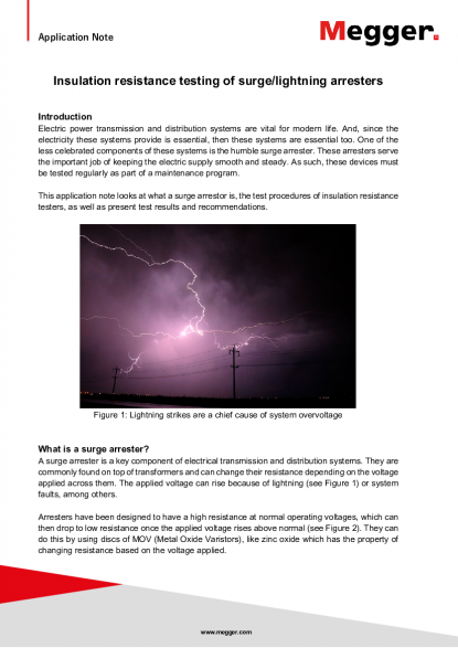
Application Note www.megger.com Insulation resistance testing of surge/lightning arresters Introduction Electric power transmission and distribution systems are vital for modern life. And, since the electricity these systems provide is essential, then these systems are essential too. One of the less celebrated components of these systems is the humble surge arrester. These arresters serve the important job of keeping the electric supply smooth and steady. As such, these devices must be tested regularly as part of a maintenance program. This application note looks at what a surge arrestor is, the test procedures of insulation resistance testers, as well as present test results and recommendations. Figure 1: Lightning strikes are a chief cause of system overvoltage What is a surge arrester? A surge arrester is a key component of electrical transmission and distribution systems. They are commonly found on top of transformers and can change their resistance depending on the voltage applied across them. The applied voltage can rise because of lightning (see Figure 1) or system faults, among others. Arresters have been designed to have a high resistance at normal operating voltages, which can then drop to low resistance once the applied voltage rises above normal (see Figure 2). They can do this by using discs of MOV (Metal Oxide Varistors), like zinc oxide which has the property of changing resistance based on the voltage applied.
Application Note www.megger.com Figure 2: Current vs voltage curve of a maximum continuous operating voltage arrester Image from Arrester Work “Arrester Reference Voltage” link As can be seen in the graph of Figure 2, an arrester has a high and constant (straight line) resistance in the operating range. Above that, the resistance drops dramatically allowing a lot of current to pass through it. So, an arrester’s main task is to maintain the optimal voltage condition of the other parts of the system by diverting or drawing excess electric power away. They are installed by connecting one side to earth/ground and the other to the system but in parallel with the asset they are protecting. Usually, the arrester is protecting a transformer (see Figure 3). Figure 3: Arrester connected to earth/ground and in parallel to a transformer
Application Note www.megger.com Test connections Follow mandated safety procedures when connecting and disconnecting to an asset Please note that testing at these voltages can be very dangerous unless you take the necessary precautions, these include but are not limited to: • Correct use of PPE e.g. electrically certified safety boots, safety gloves etc. • Making sure the equipment has been discharged and safely connected to earth/ground • Making sure that the test subject and the equipment are isolated to make the test as safe as possible • Test with a voltmeter before proceeding to make sure there are no hazardous voltages present • Visually inspect all equipment for damage/faults before any testing Insulation testing an arrester must be done based on its rated voltage. So, always test with at least 50 % of the rated voltage no more than 120 %. For example, a 10 kV rated arrestor can be tested with at least 5 kV and no more than 12 kV. This is necessary because this is the range where an arrester’s resistance is constant while also being a high number. Figure 4: Connections for testing a surge arrester using an insulation resistance tester
Application Note www.megger.com Use the appropriate size test clips for the arrester under test and attach the black lead to the top of the arrestor and the red lead to the bottom. Finally, attach the blue lead to the middle of the arrester using a conductive tape or wire (see Figure 4). The three terminals play an important role in the measurement. The test voltage is applied between the black and red terminals, while the blue terminal is for measuring surface leakage to discount it from the final result. The blue terminal is the guard terminal, and it is vital for getting an accurate measurement of resistance. Figure 5: The flow of test current and effectiveness of guard connection Test procedures The test must be done with consistency, so use the same test voltage setting and apply the test voltage for the same amount of time each time. It is recommended that the test voltage is applied for at least 15 s, but optimally 60 s. Repeat the test 3 times, taking the average reading as the result. A repeatable result is indicative of a good measurement process. A good medium voltage (1 kV to 30 kV) arrester should have a very high resistance of gigaohm to terohm range at its operating voltage range and arresters of the same type and voltage rating should have very similar resistance values. Any arrester that shows a low resistance value is faulty and must be replaced or refurbished. If a test voltage is applied that is greater than 120 % of the arrester’s rated voltage, then it will result in a lower-than-expected resistance value even when the arrester is not faulty. Therefore, it is best to stay within the recommended test voltage range of 50 % to 120 % of the arrester’s rated voltage.
Application Note www.megger.com Test results and recommendations A test was done on a selection of 15.3 kV rated surge arresters. The test parameters were: • 15 kV applied test voltage • 30 seconds of applied test voltage each time • No filters of special settings used • 3 tests were done on each arrester, but only after fully discharging each time • PASS/FAIL level was determined to be 1 GΩ based on manufacturer’s information Arrester ID Test 1 (MΩ) Test 2 (MΩ) Test 3 (MΩ) Average (MΩ) Result 12001 839 919 909 889 FAIL 12003 1115 1212 1206 1178 PASS 12004 1190 1174 1146 1170 PASS 12008 999 1066 1038 1034 PASS Table 1: Test results for a selection of 15.3 kV surge arresters It is highly recommended to check surge arresters regularly. The test for them is simple and quick, and it needs to be done. A faulty arrester can result in severe damage to expensive assets, like transformers. Therefore, regularly following the simple process from this application note can save money and maintain a smooth and steady electric power supply.